Imagine you are repairing a damaged electrical extension cord. The wire looks normal from the outside, but the appliance connected to it is not working. You suspect that the wire inside might be broken somewhere. Instead of replacing the entire cable, an electrician uses a continuity tester to quickly check whether the electrical path inside the wire is complete or broken.
A continuity tester is one of the simplest yet most important tools used in electrical troubleshooting. It helps technicians determine whether electricity can flow through a circuit or component. If the circuit path is complete, the tester confirms continuity. If the path is broken, the tester indicates a fault.
For electrical students, technicians, engineers, and beginners, learning how to use a continuity tester is a basic but essential skill. It is commonly used to test wires, switches, fuses, and circuit connections.
In this guide, you will learn the continuity tester working principle, different types of continuity testers, key components, advantages and disadvantages, and practical continuity tester applications. By the end of this article, you will clearly understand how this tool works and how it helps detect electrical faults quickly and safely.
What is a Continuity Tester?
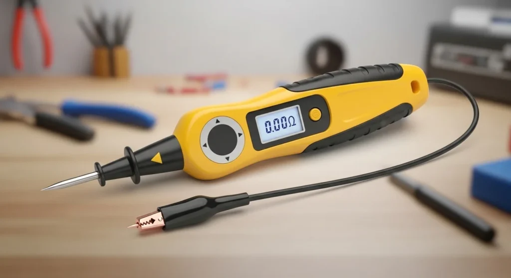
A continuity tester is an electrical testing device used to check whether an electrical circuit is complete and allows current to flow.
The tester sends a small electrical signal through the circuit. If the circuit path is complete, the device indicates continuity using a light, sound, or meter reading.
Simple Explanation
A continuity tester helps answer a simple question:
Is the electrical path complete or broken?
If electricity can pass through the circuit, the tester confirms continuity.
If electricity cannot pass, it indicates an open circuit.
Practical Example
Suppose a technician wants to check whether a fuse is blown.
The probes of the continuity tester are connected to both ends of the fuse.
- If the tester lights up or beeps, the fuse is good.
- If there is no signal, the fuse is blown.
This quick test helps technicians identify faulty components easily.
Continuity Tester Working Principle
Understanding the continuity tester working principle helps beginners use the tool correctly.
A continuity tester works by sending a small electrical current through a circuit and checking whether that current can flow through the tested path.
Step-by-Step Working Process
- Power Source ActivationThe tester contains a small battery that supplies electrical power.
- Circuit ConnectionTwo probes are connected to the points being tested.
- Current Flow TestThe tester sends a small current through the circuit.
- Continuity DetectionIf the circuit path is complete, current flows through it.
- Indicator ActivationThe tester activates an indicator such as:
- LED light
- Buzzer sound
- Meter reading
Simple Analogy
Think of a continuity tester like checking whether a water pipe is blocked. If water flows from one end to the other, the pipe is clear. If water stops somewhere, the pipe is blocked.
Similarly, if current flows through a wire, the circuit has continuity.
Types / Classification of Continuity Testers
Continuity testers come in several types depending on their design and features.
Simple Lamp Continuity Tester
This is the most basic type of tester.
Characteristics:
- Uses a small bulb as an indicator
- Simple design
- Low cost
When the circuit is complete, the bulb lights up.
Buzzer Continuity Tester
This tester uses a buzzer sound to indicate continuity.
Features include:
- Audible signal when continuity exists
- Useful when visual indicators are difficult to see
- Commonly used by electricians
Digital Continuity Tester
Digital testers use electronic circuits and displays.
Key features:
- High accuracy
- LED or digital screen indicators
- Often integrated into digital multimeters
Multimeter Continuity Mode
Most digital multimeters include a continuity testing function.
In this mode:
- The meter produces a beep when the circuit is continuous
- Resistance value may also be displayed
Main Components of a Continuity Tester
A continuity tester consists of several simple components that perform the testing function.
Power Source
The tester contains a small battery that supplies the test current.
Without this battery, the tester cannot operate.
Test Probes
Test probes connect the tester to the circuit.
They allow the current to flow through the component being tested.
Indicator
The indicator shows the test result.
Common indicators include:
- LED light
- Bulb
- Buzzer
- Digital display
Internal Resistor
The resistor controls the amount of current flowing through the circuit during testing.
This protects both the tester and the circuit components.
Housing or Body
The body of the tester holds all internal components and protects them from damage.
Continuity Tester Advantages and Disadvantages
Understanding continuity tester advantages and disadvantages helps users apply the tool effectively.
Advantages
- Simple and easy to use
- Quick circuit testing
- Affordable electrical tool
- Portable and lightweight
- Useful for troubleshooting wiring faults
- Safe for low-voltage testing
Disadvantages / Limitations
- Cannot measure voltage or current
- Limited to continuity checking only
- Requires battery for operation
- Not suitable for high-voltage circuits
Despite these limitations, continuity testers remain extremely useful for quick electrical checks.
Continuity Tester Applications
Continuity testers are widely used in electrical maintenance and repair work.
Wiring Inspection
One of the most common continuity tester applications is checking electrical wiring for breaks or faults.
Fuse Testing
Technicians use continuity testers to determine whether a fuse is blown.
Switch Testing
Continuity testers check whether switches are functioning correctly.
Appliance Repair
Electricians test internal wiring of appliances to locate faults.
Circuit Board Inspection
Technicians use continuity testers to verify connections on printed circuit boards.
Comparison Section
Difference Between Continuity Tester and Multimeter
| Feature | Continuity Tester | Multimeter |
|---|---|---|
| Main Function | Checks circuit continuity | Measures voltage, current, resistance |
| Complexity | Simple tool | More advanced |
| Measurement Types | Only continuity | Multiple measurements |
| Cost | Low | Higher |
| Usage | Quick testing | Detailed electrical analysis |
Understanding the difference between continuity tester and multimeter helps technicians select the correct tool for different tasks.
Selection Guide
Choosing the right continuity tester depends on several factors.
Type of Work
For simple wiring checks, a basic tester is sufficient.
For professional use, digital testers provide better reliability.
Indicator Type
Select testers with both visual and audible indicators for easier operation.
Build Quality
Durable testers with strong probes last longer and provide accurate results.
Safety Features
Choose testers designed for electrical work with proper insulation and protection.
Beginners should select simple and easy-to-use models.
Common Problems & Solutions
Why is the tester not indicating continuity?
Possible causes:
- Dead battery
- Loose probe connection
Solution: Replace battery and check probe contacts.
Why is the tester always showing continuity?
Possible causes:
- Internal short circuit
- Damaged wiring inside the tester
Solution: Inspect and repair the tester.
Why does the indicator light appear dim?
Possible causes:
- Weak battery
- Poor probe contact
Solution: Replace battery and ensure proper connection.
Why does the buzzer not sound?
Possible causes:
- Faulty buzzer
- Internal circuit damage
Solution: Repair or replace the tester.
Future Trends
Electrical testing tools continue to evolve with new technologies.
Smart Testing Devices
Modern testers may include digital displays and advanced diagnostic features.
Integration with Digital Tools
Future testers may connect with mobile devices for recording test results.
Improved Safety Designs
Manufacturers are developing testers with better insulation and protection.
Multi-Function Testers
Many devices now combine continuity testing with voltage and resistance measurement.
Conclusion
A continuity tester is a simple but extremely useful tool for electricians, technicians, and electrical students. It allows quick verification of electrical connections and helps detect broken wires, faulty switches, and blown fuses.
In this article, we discussed the continuity tester working principle, types of testers, major components, advantages and disadvantages, and important continuity tester applications. We also explained the difference between continuity tester and multimeter and provided a practical guide for selecting and troubleshooting the device.
Learning how to use a continuity tester properly helps technicians identify electrical faults quickly and efficiently. For beginners in electrical engineering and maintenance, mastering this tool is an important step toward developing strong troubleshooting skills.