
Introduction
Imagine a factory that runs dozens of motors every day. At the end of the month, the owner receives an electricity bill that is much higher than expected. The machines did not consume more power, yet the bill went up. What went wrong? The answer is poor power factor.
Most industrial loads, such as motors and transformers, draw reactive power in addition to useful power. This reactive power does no real work, but the utility must still supply it — and many utilities charge a penalty when power factor drops below 0.9.
A capacitor bank is the most common and cost-effective solution to this problem. It supplies reactive power locally, right where it is needed, so the utility does not have to deliver it. In this guide, you will learn what a capacitor bank is, how capacitor bank working principle operates, how to size one, how it is connected, and where capacitor bank applications are found in real life. You will also see the capacitor bank advantages and disadvantages explained in simple words.
What Is a Capacitor Bank?
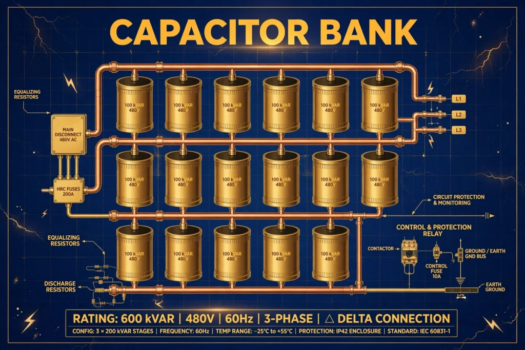
A capacitor bank is a group of capacitors connected together to supply reactive power to an electrical system. A single capacitor is a small device that stores electrical charge. When many capacitors are combined in series or parallel arrangements, they form a bank that can handle the reactive power needs of a factory, a building, or even a substation.
Think of it like a water tank placed near your house. Instead of waiting for water to travel all the way from a distant reservoir every time you open a tap, the nearby tank supplies water instantly. In the same way, a capacitor bank supplies reactive power locally, so it does not have to travel through long transmission lines from the power station.
A practical example: a manufacturing plant has a power factor of 0.75 and pays a penalty every month. An engineer installs a 200 kVAr capacitor bank near the main distribution panel. The power factor rises to 0.96, the penalty disappears, and the bank pays for itself within a year.
Working Principle
The capacitor bank working principle is based on the opposite behavior of inductors and capacitors in an AC circuit. Here is how it works, step by step:
- Inductive loads absorb reactive power. Motors, transformers, and fluorescent lamps create magnetic fields. These magnetic fields need reactive power, which flows back and forth between the source and the load without doing useful work.
- Capacitors supply reactive power. A capacitor creates an electric field instead of a magnetic field. In AC circuits, capacitors deliver reactive power with the opposite sign to inductors.
- Opposite reactive powers cancel out. When a capacitor bank is connected near an inductive load, the reactive power from the capacitors cancels the reactive power demanded by the load. This is called reactive power compensation.
- The supply sees a better power factor. With most reactive power cancelled locally, the current drawn from the utility drops. Less current means lower losses in cables and transformers, and a power factor closer to 1.0.
A simple analogy: imagine two people pushing a heavy cart in opposite directions with equal force. The cart does not move, but both work hard. Similarly, the capacitor bank removes the wasted “opposite pushing” of reactive power, so the system works more efficiently.
Types of Capacitor Bank
Fixed Capacitor Bank
A fixed capacitor bank has a constant reactive power rating. It is always connected and always supplies the same amount of reactive power. Fixed banks are simple, cheap, and reliable. They are best for loads that stay nearly constant, such as a single large motor that runs all day. The main risk is overcompensation: if the load drops, the bank can push the power factor into the leading region, which can raise voltage too much.
Automatic Capacitor Bank (APFC Panel)
An automatic power factor correction panel switches capacitor steps in and out based on the actual load. A controller measures the power factor continuously and connects or disconnects capacitor units as needed. These banks are ideal for factories where motors start and stop throughout the day. They cost more than fixed banks, but they keep the power factor in the target range at all times without manual attention.
Detuned Capacitor Bank
A detuned capacitor bank includes a series reactor (inductor) with each capacitor step. The reactor shifts the resonance frequency of the bank away from common harmonic frequencies. This type is used in plants with many variable frequency drives, UPS systems, or other harmonic-producing equipment. Without detuning, harmonics can overheat and destroy ordinary capacitors.
Medium and High Voltage Capacitor Bank
Large substations use capacitor banks rated for 11 kV, 33 kV, or higher to support the network by maintaining voltage levels and reducing losses. They are built with many capacitor cans in series-parallel groups, protected by fuses and controlled by circuit breakers.
Main Components
A capacitor bank is more than just capacitors. A complete installation includes several important parts:
- Capacitor units (cans): The heart of the bank. Each unit is rated in kVAr at a specific voltage. Multiple units are combined to reach the total required rating.
- Contactors or circuit breakers: Switch the capacitor steps in and out. Special capacitor-duty contactors handle the high inrush current that occurs when a capacitor is first energized.
- APFC controller (in automatic banks): Measures voltage, current, and power factor, then decides how many capacitor steps to connect. It is the brain of the system.
- Detuning reactors (optional): Series inductors that protect capacitors from harmonic resonance in polluted networks.
- Fuses: Protect each capacitor unit or group. If one unit fails, its fuse blows and isolates it without shutting down the whole bank.
- Discharge resistors: Safely discharge the capacitors within a minute after disconnection, so maintenance staff are not exposed to stored charge.
- Enclosure/panel: Houses everything safely, with ventilation, earthing, and warning labels.
Advantages
- Lower electricity bills: Utilities reward a high power factor and penalize a low one. A capacitor bank removes penalty charges and can cut the demand portion of the bill.
- Reduced losses: Lower current in cables and transformers means lower I²R heating losses, so less energy is wasted as heat.
- Released system capacity: With less reactive current flowing, existing transformers, cables, and switchgear can serve more useful load without expensive upgrades.
- Better voltage regulation: Capacitor banks support voltage levels, especially at the far end of long feeders where voltage tends to sag.
- Long life and fast payback: Capacitors have no moving parts and can run 10 to 15 years with only periodic inspection. In plants with penalties, a bank often pays for itself within 6 to 18 months.
Disadvantages and Limitations
- Overcompensation risk: A fixed bank sized for peak load will overcorrect when the load is light. This creates a leading power factor, which can raise voltage above safe limits.
- Harmonic sensitivity: Ordinary capacitors can resonate with system inductance at harmonic frequencies, causing overheating and premature failure. Plants with drives and UPS units need detuned banks, which cost more.
- Switching transients: Energizing a capacitor draws a large inrush current and can create voltage spikes. Proper switching devices and, in large banks, inrush reactors are required.
- No help for harmonics or unbalance: A capacitor bank corrects displacement power factor only. It does not filter harmonics or balance unbalanced loads — those need filters or other equipment.
- Maintenance and safety needs: Capacitors age, fuses blow, and contactors wear out — without periodic checks, steps fail silently and penalties return. Capacitors also store charge after disconnection, so proper discharge resistors and lockout procedures are essential.
Applications
Capacitor bank applications are found everywhere reactive power is a problem, from factories to substations:
- Industrial plants: The most common use. Factories with many motors install APFC panels at the main distribution board to avoid penalties and reduce losses.
- Commercial buildings: Shopping malls, hospitals, and office complexes with large HVAC systems use capacitor banks to keep power factor above utility limits.
- Substations: Utilities install medium and high voltage capacitor banks to support grid voltage and reduce transmission losses.
- Motor terminals: Individual large motors sometimes get their own fixed capacitor connected directly at the motor terminals for local compensation.
- Renewable energy plants: Wind and solar farms use capacitor banks (along with more advanced devices) to meet grid reactive power requirements.
- Agricultural pumping: Irrigation pump sets, which run induction motors for long hours, benefit greatly from simple fixed capacitor banks.
Capacitor Bank Comparison
| Feature | Fixed Capacitor Bank | Automatic (APFC) Bank | Detuned Bank |
|---|---|---|---|
| Reactive power output | Constant | Varies with load | Varies with load |
| Best for | Steady, constant loads | Fluctuating loads | Loads with harmonics |
| Initial cost | Low | Medium | High |
| Overcompensation risk | High at light load | Very low | Very low |
| Harmonic protection | None | None | Built-in reactors |
| Maintenance effort | Low | Medium | Medium |
| Typical payback | 6–12 months | 8–18 months | 12–24 months |
How to Choose the Right Capacitor Bank
Selecting the right bank starts with sizing. The required reactive power in kVAr is calculated from the present and target power factor: kVAr = kW × (tan φ₁ − tan φ₂). For example, a 100 kW load at 0.75 power factor needs about 54 kVAr to reach 0.95. Most engineers target 0.95 rather than a perfect 1.0, leaving a small safety margin against overcompensation.
Next, decide between fixed and automatic. For steady loads — one or two big motors running all day — a fixed bank is enough and cheaper. If motors start and stop through the day, choose an automatic APFC panel with 4 to 8 steps so the controller can match the load closely.
Check for harmonics before buying. If the plant has variable frequency drives or large UPS systems, insist on a detuned bank with series reactors. Also verify the voltage rating: in networks with fluctuations, a slightly higher rated voltage gives longer capacitor life.
Beginner tips: never size a bank by guessing — always measure the real load with a power analyzer for at least one full production cycle. Keep 10 to 20 percent spare capacity for future load growth, and make sure the panel has proper ventilation, because capacitors lose life quickly when they run hot.
Common Problems and Solutions
Q: Why did my power factor penalty come back after a year?
A: One or more capacitor steps have probably failed. Blown fuses, worn contactors, or aged capacitors reduce the bank’s output silently. Inspect each step with a clamp meter and replace faulty units.
Q: The capacitors are bulging or leaking oil. What should I do?
A: Switch the bank off immediately and replace the damaged units. Bulging is a sign of overheating or overvoltage. Check the system voltage and harmonic levels before installing replacements.
Q: Can a capacitor bank cause overvoltage?
A: Yes, if it overcompensates at light load. The voltage can rise above the rated value, especially at the far end of feeders. Use an automatic bank or reduce the fixed bank size to prevent this.
Q: Do capacitor banks work with generators?
A: They can, but carefully. Keep the power factor slightly lagging (around 0.95) and never let the bank push it into the leading region when running on generator supply.
Q: How often should a capacitor bank be maintained?
A: Every 6 to 12 months. Check for bulging cans, measure step currents, tighten connections, clean dust, and verify controller readings against a handheld meter.
Q: What is the difference between a capacitor bank and a synchronous condenser?
A: Both supply reactive power, but a capacitor bank is static with fixed steps, while a synchronous condenser is a rotating machine that can vary its output smoothly. Capacitor banks are far cheaper and need less maintenance, which is why they dominate industrial use.
Future Trends
Capacitor banks are evolving with smarter technology. Modern APFC controllers now come with communication ports that send power factor, voltage, and harmonic data to plant monitoring systems. Facility managers can watch their power factor on a phone and receive alerts before a penalty appears on the bill.
Hybrid compensation is another growing trend. In plants with severe harmonics, engineers combine detuned capacitor banks with active harmonic filters. The capacitors handle the bulk reactive power cheaply, while the active filter cleans up harmonics.
Looking ahead, as industries add more solar inverters and electric vehicle chargers, reactive power behavior is becoming more dynamic. Still, for straightforward power factor correction, the humble capacitor bank remains the most economical choice and is unlikely to disappear.
Conclusion
A capacitor bank is a simple, proven, and economical way to correct power factor. By supplying reactive power locally, it reduces electricity bills, cuts energy losses, frees up system capacity, and improves voltage regulation. Choosing between fixed, automatic, and detuned types depends on how steady your load is and whether harmonics are present in your network.
Proper sizing is the key to success — measure the real load, target a power factor of about 0.95, and leave room for growth. Regular inspection keeps the bank healthy for many years. If your facility pays power factor penalties today, a capacitor bank is very likely the fastest-paying investment you can make. Keep learning, measure before you buy, and let the savings speak for themselves.