Imagine a simple string of decorative lights used during festivals. When you plug them into a power outlet, all the bulbs light up together. However, if one bulb stops working, the entire string of lights goes off. This situation is a classic example of a Series Circuit in electrical systems.
Series circuits are one of the most basic and fundamental circuit configurations used in electrical and electronic systems. For electrical students, engineers, and technicians, understanding how a series circuit works is essential because it forms the foundation of circuit analysis and electrical design.
In electrical engineering, circuits can be connected in different ways to control how current flows through components. Among these configurations, series circuits are the simplest and easiest to understand. They help beginners learn about voltage distribution, current flow, and resistance behavior.
In this article, you will learn the Series Circuits working principle, their types, components, and practical Series Circuits applications. We will also explain the Series Circuits advantages and disadvantages, compare them with parallel circuits, and discuss common problems and solutions in real electrical systems.
What is a Series Circuit?
Definition
A Series Circuit is an electrical circuit in which all components are connected in a single path so that the same current flows through each component.
Simple Explanation
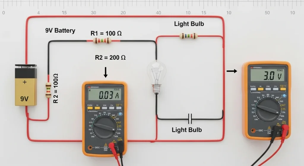
In a series circuit, electrical components such as resistors, lamps, or batteries are connected one after another in a single loop. Because there is only one path for the current to flow, the same current passes through every component in the circuit.
Practical Example
A simple example of a series circuit is a flashlight. Inside the flashlight, the battery, switch, and bulb are connected in series. When the switch is turned on, current flows through the battery, switch, and bulb in one continuous path.
If any component in the series circuit breaks, the entire circuit stops working.
Series Circuits Working Principle
The Series Circuits working principle is based on the idea that electric current flows through a single continuous path.
All components share the same current, but the voltage is divided among the components depending on their resistance.
Step-by-Step Working Process
- Power Supply Provides Voltage
A battery or power source provides electrical energy to the circuit.
- Current Flows Through One Path
Electric current flows through a single path connecting all components.
- Current Passes Through Each Component
The same current flows through every resistor, bulb, or device in the circuit.
- Voltage Division Occurs
The total voltage from the source is divided across each component.
- Circuit Completes the Loop
The current returns to the power source after passing through all components.
Simple Analogy
Think of a series circuit like people standing in a single line passing a bucket of water. The bucket moves from one person to another in the same path. If one person leaves the line, the flow stops.
Types of Series Circuits
Series circuits can be classified based on their electrical characteristics and applications.
Resistive Series Circuit
A resistive series circuit contains resistors connected in series with a voltage source.
Features:
- Used in basic electrical experiments
- Helps study voltage division
- Common in teaching laboratories
Series Circuit with Lamps
This type of circuit uses bulbs connected in series.
Features:
- Used in decorative lighting
- Used in early Christmas lights
- Demonstrates how one failed bulb affects the entire circuit
Series Battery Circuit
Multiple batteries connected in series increase the total voltage output.
Features:
- Used in flashlights
- Used in battery packs
- Used in portable electronic devices
Main Components of a Series Circuit
A series circuit contains several basic electrical components.
Power Source
The power source provides electrical energy. It can be a battery, power supply, or generator.
Conductors (Wires)
Wires connect all components and allow current to flow through the circuit.
Electrical Load
Loads are components that use electrical energy. Examples include resistors, bulbs, motors, or heaters.
Switch
A switch controls the flow of current by opening or closing the circuit.
Protection Devices
Fuses or circuit breakers may be used to protect the circuit from overcurrent.
Series Circuits Advantages
Understanding the Series Circuits advantages and disadvantages helps engineers choose the right circuit configuration.
Advantages
- Simple circuit design
- Easy to build and understand
- Requires fewer wires compared to other circuits
- Useful for learning basic electrical principles
- Easy to calculate total resistance and current
These advantages make series circuits ideal for educational purposes and simple electrical devices.
Series Circuits Disadvantages / Limitations
Despite their simplicity, series circuits have several limitations.
Disadvantages
- If one component fails, the entire circuit stops working
- Voltage is divided among components
- Not suitable for large electrical systems
- Devices cannot operate independently
- Total resistance increases when more components are added
Because of these limitations, most modern electrical systems use parallel circuits instead.
Series Circuits Applications
There are several practical Series Circuits applications in electrical and electronic systems.
Decorative Lighting
Some decorative lights and holiday light strings use series circuits.
Flashlights
Flashlights use batteries connected in series to increase voltage.
Battery Packs
Many battery-powered devices use series-connected batteries.
Voltage Divider Circuits
Series circuits are used in electronics to divide voltage between components.
Educational Experiments
Series circuits are commonly used in electrical laboratories to teach basic circuit concepts.
Comparison: Series Circuit vs Parallel Circuit
Understanding the difference between series circuit and parallel circuit is important for electrical engineers.
| Feature | Series Circuit | Parallel Circuit |
|---|---|---|
| Current Path | Single path | Multiple paths |
| Current Flow | Same current in all components | Current splits between branches |
| Voltage | Divided among components | Same voltage across components |
| Failure Effect | One failure stops entire circuit | Other branches continue working |
| Complexity | Simple | More complex |
Parallel circuits are commonly used in homes because devices operate independently.
Selection Guide: When to Use Series Circuits
Engineers choose series circuits in specific situations.
When Simple Design is Required
Series circuits are suitable for simple electrical systems.
For Learning and Training
Educational institutions use series circuits to teach electrical fundamentals.
When Voltage Needs to be Increased
Batteries connected in series increase total voltage.
For Voltage Divider Applications
Series resistors are commonly used in electronic circuits to control voltage levels.
For beginners, series circuits provide the easiest way to understand electrical current flow.
Common Problems & Solutions
Problem 1: Entire Circuit Stops Working
Cause:
One component in the series circuit has failed.
Solution:
Check each component and replace the faulty one.
Problem 2: Reduced Brightness in Bulbs
Cause:
Adding more bulbs increases total resistance.
Solution:
Reduce the number of loads or increase the supply voltage.
Problem 3: Voltage Drop Issues
Cause:
Voltage is divided across components.
Solution:
Use components with proper resistance values.
Problem 4: Excessive Heat in Resistors
Cause:
High current flow may produce heat.
Solution:
Use resistors with proper power rating.
Future Trends in Circuit Design
Although simple series circuits are basic, modern circuit systems combine series and parallel configurations.
Integrated Circuits
Modern electronics use integrated circuits that contain complex networks of series and parallel components.
Smart Electrical Systems
Smart devices and automated systems use advanced circuit designs based on fundamental series and parallel principles.
Energy Efficient Designs
New electrical designs focus on improving efficiency and reducing energy losses in circuits.
Understanding series circuits remains important because they are the foundation of all electrical circuit designs.
Conclusion
A Series Circuit is one of the most basic electrical circuit configurations where components are connected in a single path. The same current flows through every component, while the total voltage is divided across them.
Learning the Series Circuits working principle helps electrical students and beginners understand fundamental electrical concepts such as current flow, resistance, and voltage distribution. Series circuits are easy to design, simple to analyze, and widely used in educational experiments and small electrical devices.
However, the Series Circuits advantages and disadvantages must be considered carefully. While they are simple and cost-effective, the failure of one component can stop the entire circuit. Because of this limitation, most large electrical systems prefer parallel circuits.
Despite these limitations, understanding series circuits is essential for anyone studying electrical engineering or working with electrical systems.