You are standing in front of an electrical control panel with a printed circuit diagram in your hand. The paper is full of lines, circles, zigzag shapes, and strange markings. You know the system should control motors and lights, but you cannot understand what those symbols mean. Without understanding the drawing, you cannot troubleshoot or install the system correctly.
This is where learning How to Read Electrical Symbols becomes essential.
Electrical symbols are the universal language of electrical engineering. Whether you are working on home wiring, industrial panels, or automation systems, you must understand circuit symbols to do your job properly and safely.
If you misread a symbol, you may connect wires incorrectly, damage equipment, or create a serious safety risk.
In this article, you will learn:
- What electrical symbols are
- The How to Read Electrical Symbols working principle
- Different types of electrical symbols
- Their applications in real projects
- Common mistakes and solutions
By the end, you will be able to confidently read basic electrical drawings like a professional.
2. What is How to Read Electrical Symbols?
Definition
How to Read Electrical Symbols refers to the ability to understand and interpret standard graphical signs used in electrical diagrams to represent components and connections.
These symbols represent real electrical devices such as switches, resistors, motors, transformers, and circuit breakers.
Simple Explanation
Think of electrical symbols like road signs.
- A red octagon means STOP.
- A triangle means warning.
Similarly:
- A zigzag line means resistor.
- A circle with “M” means motor.
- Two parallel lines mean capacitor.
Each symbol has a fixed meaning.
Practical Example
When you see this in a diagram:
- Battery symbol → Power source
- Switch symbol → On/Off control
- Bulb symbol → Load
If you can identify these correctly, you can understand the whole circuit.
3. Working Principle
How to Read Electrical Symbols Working Principle
Electrical drawings follow standard rules. Symbols replace real components to make diagrams simple and clear.
Step-by-Step Process
- Identify the power source.
- Follow the line connections.
- Recognize each symbol.
- Understand component function.
- Analyze current flow direction.
Easy Analogy
Imagine reading a map:
- Roads = Wires
- Cities = Components
- Direction arrows = Current flow
If you know map symbols, you can reach your destination.
If you know circuit symbols, you can understand the system.
Key Principles
- Symbols are standardized
- Lines represent wires
- Junction dots mean connection
- No dot means crossing without connection
This explains the How to Read Electrical Symbols working principle.
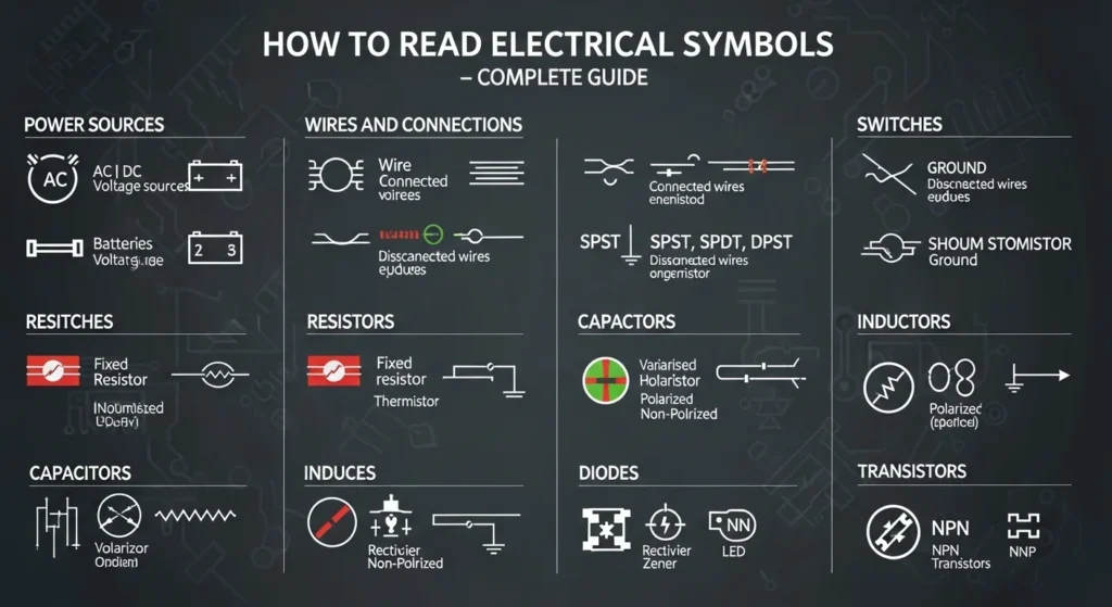
4. Types / Classification
Electrical symbols are classified based on their function.
H3: Power Source Symbols
These represent supply sources.
- Battery
- AC supply
- DC supply
- Generator
Used at the start of diagrams.
Passive Component Symbols
These control current flow.
- Resistor
- Capacitor
- Inductor
- Fuse
These components limit, store, or filter energy.
Switching Device Symbols
Used to control circuits.
- SPST switch
- Push button
- Relay
- Circuit breaker
These symbols are common in control panels.
Load Symbols
Represent electrical devices.
- Lamp
- Motor
- Heater
- Buzzer
Loads consume electrical energy.
Protection Device Symbols
Used for safety.
- MCB
- RCCB
- Fuse
- Earth symbol
These prevent damage and shock.
Control and Automation Symbols
Used in industrial systems.
- Contactor
- Timer
- Limit switch
- PLC
Important in motor control circuits.
5. Main Components
Understanding symbols requires knowing major parts of a diagram.
1. Lines (Conductors)
Represent wires connecting components.
2. Junction Dot
Indicates electrical connection.
3. Reference Numbers
Help identify components.
4. Labels and Ratings
Show voltage, current, or power values.
5. Legend / Key Table
Explains symbol meanings.
Each element improves clarity and accuracy.
6. Advantages
How to Read Electrical Symbols Advantages
- Easy circuit understanding
- Faster troubleshooting
- Accurate installation
- Reduced wiring mistakes
- Improved safety
- Better communication among engineers
- Saves time in projects
These points show the How to Read Electrical Symbols advantages and disadvantages clearly.
7. Disadvantages / Limitations
There are some limitations.
- Beginners feel confused initially
- Different countries may use slight variations
- Complex industrial drawings are difficult
- Requires practice
- Misinterpretation can cause errors
However, practice removes these difficulties.
8. Applications
How to Read Electrical Symbols Applications
Home Wiring
- Switchboard layout
- Lighting circuits
- Socket connections
Industrial Use
- Motor control circuits
- Control panels
- Power distribution systems
Electronics
- PCB diagrams
- Electronic devices
Modern Technology
- Solar systems
- Smart homes
- Automation systems
Electrical symbols are used in every electrical project.
9. Comparison Section
Difference Between Electrical Symbols and Wiring Diagrams
| Feature | Electrical Symbols | Wiring Diagram |
| Purpose | Represent components | Show actual connections |
| Detail Level | Basic representation | Detailed layout |
| Usage | Circuit understanding | Installation guide |
| Appearance | Simplified | Realistic wiring path |
| Complexity | Simple to moderate | Can be complex |
Understanding the difference between electrical symbols and wiring diagram is important for beginners.
10. Selection Guide
How to Learn and Choose the Right Diagram
1. Start with Basic Symbols
Learn common symbols first.
2. Use Standard Charts
Refer to IEC or ANSI standard charts.
3. Practice Simple Circuits
Start with lamp and switch diagrams.
4. Study Motor Control Circuits
Move to advanced diagrams gradually.
5. Use Simulation Software
Practice safely before real installation.
Tips for Beginners
- Memorize common symbols
- Follow current path
- Check legend table
- Avoid assumptions
- Practice daily
11. Common Problems & Solutions
Q1: I cannot understand where the circuit starts.
Solution: Locate power source symbol first.
Q2: Lines cross but do not connect. Why?
Answer: Only connected if a dot is present.
Q3: Why are some symbols different in books?
Cause: Different standards (IEC or ANSI).
Q4: How to avoid mistakes?
Solution: Double-check legend and ratings.
Q5: Can I learn without practical work?
Yes, but practical experience improves confidence.
12. Future Trends
Electrical drawing technology is evolving.
New Developments
- Digital circuit diagrams
- Smart CAD software
- 3D electrical modeling
- AI-based error detection
- Cloud-based design sharing
Industry Direction
- Paperless documentation
- Smart electrical panels
- Automated schematic generation
- Integrated IoT systems
Learning symbol reading will remain essential, even with modern tools.
13. Conclusion
Understanding How to Read Electrical Symbols is a fundamental skill for every electrical student and technician. Symbols are the universal language of electrical systems. Without this knowledge, it is impossible to read circuit diagrams correctly.
By learning basic symbols, understanding current flow, and practicing simple circuits, you can quickly improve your confidence. This skill helps in installation, troubleshooting, maintenance, and system design.
Although beginners may find diagrams confusing at first, regular practice makes them easy to understand. As a senior engineer, I strongly recommend mastering electrical symbols before working on real systems.
Keep learning, practicing, and reviewing diagrams daily. Strong basics lead to strong professional skills.