Imagine running an industrial factory where many motors, transformers, and welding machines operate simultaneously. The electricity bill suddenly becomes very high even though the useful work output is not increasing. This happens because of poor power factor.
Power factor plays a very important role in electrical power systems. Low power factor means more reactive power is flowing in the system, which increases losses and reduces system efficiency.
Understanding power factor improvement methods is essential for electrical students, engineers, technicians, and beginners working in power systems. Improving power factor helps reduce electricity cost, improve system efficiency, and increase equipment life.
In this article, you will learn what power factor is, power factor improvement working principle, types of power factor correction methods, power factor improvement applications, and power factor advantages and disadvantages — explained in simple language.
Think of this as a practical guide written from real engineering experience.
What is Power Factor Improvement?
Power factor improvement means increasing the power factor value of an electrical system toward unity (1.0).
Simple Explanation
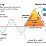
Power factor shows how efficiently electrical power is used.
- Active power (kW) → Useful work
- Reactive power (kVAR) → Magnetic field support
- Apparent power (kVA) → Total system power
If power factor is low:
- More current flows
- Transmission losses increase
- Equipment heating increases
- Electricity cost increases
Practical Example
Industrial motors usually operate at 0.7–0.85 power factor. By improving power factor to 0.95 or higher, energy efficiency can be improved.
Power Factor Improvement Working Principle
Power factor improvement working principle is based on reactive power compensation.
Step-by-Step Process
- Measure load power factor
- Calculate required reactive power compensation
- Install correction device
- Reduce reactive power demand from supply
Easy Analogy
Think of power factor like carrying a heavy bag:
- Useful work = useful items inside bag
- Reactive power = unnecessary weight
- Power factor correction = removing extra weight
The goal is to reduce reactive current flow.
Types / Classification of Power Factor Improvement Methods
1. Static Capacitor Method
This is the most common method.
- Capacitors are connected across load terminals.
- Capacitors supply reactive power locally.
- Suitable for industrial and commercial loads.
Advantages:
- Low cost
- Simple installation
- High reliability
2. Synchronous Condenser Method
- Uses synchronous motor running without mechanical load.
- Acts like variable capacitor or inductor.
Advantages:
- Smooth reactive power control
- Suitable for large power systems
Disadvantages:
- High maintenance cost
- Large size
3. Phase Advancer Method
- Used mainly in induction motor systems.
- Improves motor power factor.
Mostly used in older industrial applications.
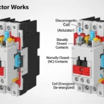
4. Automatic Power Factor Correction (APFC) System
Modern industrial plants use APFC panels.
Components include:
- Capacitor banks
- Microcontroller controller
- Switching contactors
APFC automatically adjusts reactive power compensation.
Main Components Used in Power Factor Correction
Capacitor Bank
- Main reactive power compensation device.
- Stores electrical energy.
Contactors
- Switch capacitor units automatically.
Controller Unit
- Measures power factor.
- Controls capacitor switching.
Protection Devices
- Fuse
- Circuit breaker
- Surge protection
These components ensure system safety.
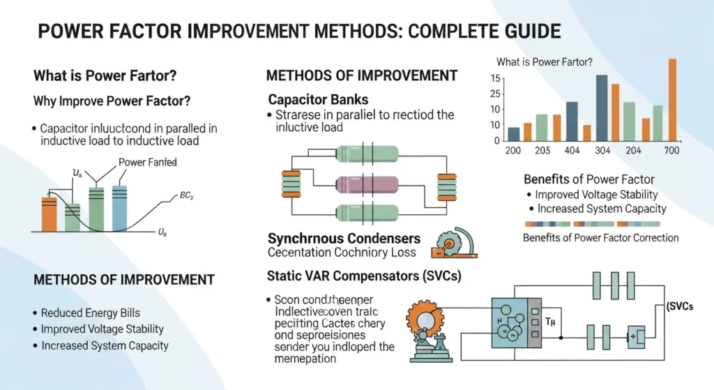
Advantages of Power Factor Improvement
Let us discuss power factor improvement methods advantages and disadvantages.
Advantages
- Reduces electricity bill
- Improves system efficiency
- Reduces line losses
- Increases transformer capacity utilization
- Reduces cable heating
- Improves voltage regulation
- Increases equipment life
Real-world benefit: Industries can save significant energy cost.
Disadvantages / Limitations
- Initial installation cost
- Overcorrection may cause leading power factor
- Maintenance requirement
- Harmonic resonance risk
- Complex system design
Engineers must design correction systems carefully.
Applications of Power Factor Improvement Methods
Power factor improvement methods applications are very wide.
Industrial Applications
- Motor-driven factories
- Steel plants
- Textile industries
- Cement plants
Commercial Applications
- Shopping malls
- Office buildings
- Hospitals
Utility Power Systems
- Transmission network stability
- Load management
- Grid efficiency improvement
Modern Technology
- Smart grid systems
- Renewable energy integration
- Electric vehicle charging stations
Comparison Section
Difference Between Passive and Active Power Factor Correction
| Feature | Passive Correction | Active Correction |
| Cost | Low | High |
| Efficiency | Good | Very high |
| Control | Fixed | Dynamic |
| Complexity | Simple | Complex |
| Application | Small systems | Large industrial systems |
This comparison helps in selecting correction method.
Selection Guide
When selecting power factor correction system:
- Calculate load kW and kVAR
- Measure existing power factor
- Consider harmonic distortion
- Choose proper capacitor rating
- Add safety margin (10–20%)
Beginner Tips
- Do not overcompensate reactive power.
- Use automatic correction for variable loads.
- Install protection devices.
- Monitor system temperature.
Common Problems & Solutions
Why does power factor become low?
Cause:
- Inductive loads like motors and transformers.
Solution:
- Install capacitor bank.
Why does capacitor overheat?
Cause:
- Harmonic distortion or overvoltage.
Solution:
- Use harmonic filter.
Why does APFC panel malfunction?
Cause:
- Sensor error
- Controller failure
Solution:
- Check wiring and calibration.
Future Trends
Power factor technology is improving.
Smart Power Factor Control
- AI-based reactive power management
- Real-time monitoring
- Predictive maintenance
Renewable Energy Systems
Solar and wind systems require advanced power factor correction.
Harmonic Filtering Technology
Modern systems use active filters to improve power quality.
Future power grids will be more intelligent and energy efficient.
Conclusion
Power factor improvement is a very important concept in modern electrical engineering. It helps reduce energy losses, improve system efficiency, and lower electricity costs. Understanding power factor improvement methods is essential for industrial and power system engineers.
We discussed power factor improvement working principle, types of correction methods, applications, and advantages and disadvantages. Proper power factor correction ensures stable voltage, reduced heating, and better equipment performance.
As a junior engineer, always focus on load analysis, harmonic control, and correct capacitor selection.
Mastering power factor improvement methods will help you design efficient and reliable electrical systems.
Keep learning and apply knowledge in real engineering practice.