Imagine the electrical wiring inside a modern home. When you switch on a fan in one room, the lights in another room continue to work normally. If one bulb burns out, the other appliances still operate. This convenient and reliable operation is possible because most household electrical systems use a parallel circuit.
Parallel circuits are one of the most fundamental concepts in electrical engineering. From home wiring systems to complex industrial control panels, this circuit configuration plays a critical role in distributing electricity safely and efficiently.
For electrical students, engineers, technicians, and beginners, understanding how parallel circuits work is essential. Without this knowledge, it becomes difficult to design safe electrical systems, troubleshoot faults, or calculate power distribution.
In this article, you will learn the parallel circuit working principle, its types, components, advantages, and limitations. We will also explore parallel circuit applications, practical troubleshooting tips, and the difference between series and parallel circuits. The goal is to explain the topic clearly and practically, just like a senior electrical engineer guiding a junior technician.
2. What is a Parallel Circuit?
A parallel circuit is an electrical circuit in which multiple components are connected across the same voltage source in separate branches.
In simple terms, each component has its own path to receive electrical current.
Key Characteristics
- Voltage across each branch is the same.
- Current divides among different branches.
- If one branch fails, the rest of the circuit continues to operate.
Simple Example
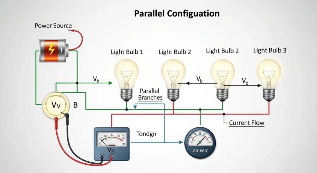
Consider three light bulbs connected to a battery:
- In a parallel circuit, each bulb is connected directly to the battery terminals.
- Each bulb receives the same voltage.
- If one bulb burns out, the others remain lit.
This is why parallel circuits are widely used in residential wiring and electrical distribution systems.
3. Parallel Circuit Working Principle
The parallel circuit working principle is based on providing multiple paths for electric current to flow from the power source.
Instead of flowing through a single path, the current splits into several branches.
Step-by-Step Operation
- Power Source Supplies Voltage
- A battery or power supply provides electrical energy.
- Branches Connect to the Same Voltage
- All components are connected across the same two points.
- Current Splits into Multiple Paths
- The total current divides between the branches.
- Each Component Operates Independently
- Each device receives full voltage.
- Total Current Equals Sum of Branch Currents
This relationship can be expressed as:
Total Current = I₁ + I₂ + I₃ + … + Iₙ
Simple Analogy
Think of a water distribution system in a building:
- The main pipe carries water.
- Several smaller pipes branch out to different apartments.
- Each apartment receives water independently.
Similarly, a parallel circuit distributes electrical current across multiple branches.
4. Types / Classification of Parallel Circuits
Parallel circuits can be classified based on the type of components used.
Pure Resistive Parallel Circuit
This type contains only resistors connected in parallel.
Characteristics:
- Voltage remains constant across each resistor
- Current divides according to resistance values
- Common in basic electrical experiments
Parallel Circuit with Capacitors
In this configuration, capacitors are connected in parallel.
Characteristics:
- Voltage across each capacitor is the same
- Total capacitance increases
- Used in filtering and energy storage circuits
Parallel Circuit with Inductors
Inductors connected in parallel form this type of circuit.
Characteristics:
- Used in power electronics
- Important in AC circuits and filters
- Affects current flow and impedance
Mixed Parallel Circuit
A mixed parallel circuit contains different components such as resistors, capacitors, and inductors.
This type is common in real electrical systems and electronic circuits.
5. Main Components of a Parallel Circuit
A parallel circuit consists of several basic components that allow electricity to flow efficiently.
Power Source
The power source provides electrical energy.
Examples:
- Battery
- Generator
- Power supply
Conductors (Wires)
Conductors connect all components and allow current to flow between branches.
Copper wires are commonly used due to low resistance.
Electrical Loads
Loads are devices that consume electrical power.
Examples include:
- Light bulbs
- Fans
- Motors
- Electronic equipment
Switches
Switches control the flow of electricity.
They allow users to turn devices on or off independently.
Protective Devices
Circuit breakers and fuses protect the circuit from overload and short circuits.
6. Parallel Circuit Advantages and Disadvantages
Understanding parallel circuit advantages and disadvantages is important for proper electrical system design.
Advantages
- Each device receives full supply voltage
- Failure of one component does not affect others
- Devices can operate independently
- Suitable for home wiring systems
- Easy to add additional branches
- Reliable for large electrical systems
These benefits make parallel circuits the preferred choice in modern electrical installations.
Disadvantages / Limitations
- Requires more wiring compared to series circuits
- Installation cost can be higher
- Current distribution may become complex in large systems
- Fault detection may be difficult in complex networks
- Short circuits can cause high current flow
Despite these limitations, the advantages usually outweigh the drawbacks.
7. Parallel Circuit Applications
Parallel circuits are widely used in both small electronic devices and large electrical systems.
Residential Wiring
Most household electrical wiring uses parallel circuits.
This allows:
- Independent operation of appliances
- Equal voltage supply to all devices
- Safe and reliable power distribution
Industrial Power Systems
Factories use parallel circuits to supply power to multiple machines simultaneously.
Each machine operates independently without affecting others.
Electronic Devices
Electronic circuits often use parallel components for:
- Voltage regulation
- Signal processing
- Circuit stability
Power Distribution Networks
Large electrical grids use parallel connections to distribute power to different regions.
This ensures reliable electricity supply.
Lighting Systems
Street lights and building lighting systems use parallel circuits so that one failed lamp does not affect others.
These examples demonstrate the importance of parallel circuit applications in modern electrical engineering.
8. Comparison Section
Difference Between Series and Parallel Circuits
| Feature | Parallel Circuit | Series Circuit |
|---|---|---|
| Current Path | Multiple paths | Single path |
| Voltage | Same across all components | Divided among components |
| Device Operation | Independent | Dependent |
| Failure Impact | Other components continue working | Entire circuit stops |
| Wiring Complexity | More wiring required | Simple wiring |
Understanding the difference between series and parallel circuits helps engineers select the correct configuration for specific applications.
9. Selection Guide
Choosing the right circuit configuration depends on several practical considerations.
Power Requirement
If multiple devices require the same voltage, a parallel circuit is ideal.
Reliability
Parallel circuits provide better reliability because devices operate independently.
Safety
For home and industrial systems, parallel circuits are safer and easier to manage.
Installation Cost
Although wiring cost may be higher, the long-term reliability makes parallel circuits cost-effective.
Expansion Capability
Parallel circuits allow easy addition of new devices without affecting existing loads.
For beginners designing electrical systems, parallel circuits are usually the best choice.
10. Common Problems & Solutions
Why are some devices not receiving power?
Possible causes:
- Loose wiring
- Broken branch connection
- Faulty switch
Solution: Inspect connections and repair damaged wires.
Why is the circuit drawing excessive current?
Possible causes:
- Short circuit
- Overloaded branches
Solution: Reduce load and check protective devices.
Why is one branch overheating?
Possible causes:
- High current in that branch
- Poor conductor quality
Solution: Use proper wire size and check load distribution.
Why do circuit breakers trip frequently?
Possible causes:
- Excessive load
- Faulty appliances
Solution: Identify overloaded devices and distribute load properly.
11. Future Trends
Electrical systems continue to evolve with new technologies.
Smart Electrical Networks
Modern smart grids use advanced monitoring to manage parallel power distribution.
Intelligent Circuit Protection
New protection devices detect faults faster and improve system safety.
Energy-Efficient Designs
Parallel circuits are being optimized to reduce energy losses.
Renewable Energy Integration
Solar panels and battery systems are connected using parallel configurations to increase power capacity.
Modular Electrical Systems
Future electrical systems will allow easy expansion using modular parallel connections.
These developments will further increase the importance of parallel circuits in electrical engineering.
12. Conclusion
A parallel circuit is one of the most important circuit configurations used in electrical systems. It allows multiple components to operate independently while receiving the same supply voltage.
In this article, we explored the parallel circuit working principle, its types, main components, advantages, disadvantages, and real-world applications. We also discussed the difference between series and parallel circuits, which helps engineers select the correct circuit design.
Parallel circuits are widely used in homes, industries, and electronic devices because they provide reliability, safety, and flexibility. Even if one device fails, the rest of the system continues to operate normally.
For electrical students and technicians, mastering parallel circuits is a foundational skill. Understanding how current divides, how loads behave, and how to troubleshoot problems will greatly improve your practical electrical knowledge.
Continuous learning and hands-on practice will help you design safer and more efficient electrical systems in the future.