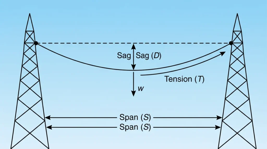

Imagine looking at overhead power lines stretched between two transmission towers. You may notice that the conductors are not perfectly straight—they hang slightly in the middle, forming a gentle curve. This curve is called sag, and the force that keeps the conductor stretched between the towers is called tension. Both sag and tension are carefully calculated to ensure the safe and reliable operation of electrical transmission and distribution systems.
Understanding Sag and Tension in Lines is essential for electrical engineering students, technicians, and engineers because incorrect sag or excessive tension can lead to conductor damage, tower failure, electrical faults, or safety hazards. Engineers must balance these two factors while considering conductor weight, span length, wind pressure, ice loading, and temperature changes.
In this guide, you will learn the Sag and Tension in Lines working principle, different types, important components, practical examples, advantages, disadvantages, applications, selection tips, troubleshooting methods, and future developments. By the end of this article, you will have a clear understanding of why sag and tension calculations are among the most important parts of transmission line design.
What is Sag and Tension in Lines?
Sag and Tension in Lines refer to two closely related mechanical properties of overhead electrical conductors.
- Sag is the vertical distance between the lowest point of the conductor and the straight line joining the two supporting towers or poles.
- Tension is the pulling force acting along the conductor that keeps it suspended between the supports.
Both values must be carefully balanced. If the conductor has too much sag, it may come dangerously close to the ground or nearby objects. If the tension is too high, the conductor or supporting structures may experience excessive mechanical stress.
Simple Explanation
Think of a rope tied tightly between two trees.
- If the rope is loose, it hangs lower in the middle. This is more sag.
- If you pull the rope tightly, it becomes straighter. This means higher tension.
Overhead electrical conductors behave in the same way.
Practical Example
Suppose an electrical utility installs a 132 kV transmission line across a highway. During hot summer weather, the conductor expands because of increased temperature, causing additional sag. Engineers calculate the correct tension during installation so that even at maximum temperature, the conductor maintains the required ground clearance and remains safe.
Sag and Tension in Lines Working Principle
The Sag and Tension in Lines working principle is based on balancing the conductor’s weight with the mechanical pulling force applied between two supports.
Gravity continuously pulls the conductor downward, while tension acts horizontally from both ends to support the conductor. The final shape formed by the conductor depends on the balance between these forces.
Step 1: Conductor Installation
The conductor is installed between two poles or transmission towers.
Step 2: Weight Acts Downward
The conductor’s own weight creates a downward force due to gravity.
Step 3: Tension Is Applied
Mechanical tension is applied during installation to support the conductor safely.
Step 4: Sag Forms Naturally
Because the conductor is flexible, it forms a curved shape instead of remaining perfectly straight.
Step 5: Environmental Conditions Affect Performance
Several external factors influence sag and tension throughout the year:
- Temperature
- Wind pressure
- Ice accumulation
- Span length
- Conductor material
- Mechanical loading
Engineers calculate these factors before constructing transmission lines to ensure safe operation under all weather conditions.
Easy Analogy
Imagine holding a heavy chain between your two hands.
- Pull harder, and the chain becomes straighter.
- Relax your hands, and the chain hangs lower.
Electrical conductors behave in exactly the same manner.
Factors Affecting Sag and Tension
Several important factors determine the amount of sag and tension in overhead transmission lines.
Conductor Weight
Heavier conductors produce greater sag because gravity exerts a larger downward force.
Span Length
Longer distances between towers result in increased sag.
Temperature
As temperature increases:
- Conductors expand.
- Sag increases.
- Tension decreases.
As temperature decreases:
- Conductors contract.
- Sag decreases.
- Tension increases.
Wind Load
Strong winds increase mechanical stress on the conductor and supporting structures.
Ice Loading
In cold regions, ice accumulation increases conductor weight, leading to higher sag and additional tension.
Conductor Material
Different materials such as:
- AAC (All Aluminium Conductor)
- ACSR (Aluminium Conductor Steel Reinforced)
- AAAC (All Aluminium Alloy Conductor)
have different mechanical strengths and expansion characteristics.
Types of Sag and Tension in Lines
Different operating conditions produce different types of sag and tension.
Normal Sag
Normal sag occurs under standard operating conditions without extreme weather.
Features
- Stable operation
- Standard conductor clearance
- Normal mechanical loading
Maximum Sag
Maximum sag occurs when conductors expand due to high temperatures or heavy loading.
Causes
- Hot summer weather
- Heavy conductor loading
- Long transmission spans
Engineers design transmission lines to safely accommodate maximum sag.
Minimum Sag
Minimum sag occurs during cold weather when conductors contract.
Characteristics
- Higher mechanical tension
- Greater stress on towers
- Increased risk if tension exceeds design limits
Initial Tension
This is the tension applied during conductor installation.
Proper initial tension ensures safe operation throughout seasonal temperature changes.
Final Operating Tension
Final operating tension is the actual tension experienced after considering:
- Temperature changes
- Wind loading
- Ice loading
- Long-term conductor creep
Engineers continuously monitor this value during transmission line maintenance.
Main Components of Sag and Tension in Lines
Several components work together to maintain the correct sag and tension in an overhead transmission line. Understanding these parts helps engineers design safe and reliable power systems.
Conductor
The conductor carries electrical power from one location to another.
Functions:
- Transmits electrical energy
- Supports its own mechanical weight
- Expands and contracts with temperature changes
Common conductor materials include:
- Aluminium
- Copper
- ACSR (Aluminium Conductor Steel Reinforced)
- AAAC (All Aluminium Alloy Conductor)
Transmission Towers or Poles
Transmission towers support the conductor above the ground.
Functions:
- Maintain required ground clearance
- Carry conductor weight
- Resist wind and mechanical forces
- Keep conductors properly spaced
Insulators
Insulators separate the energized conductor from the tower.
Functions:
- Prevent electrical leakage
- Support conductor weight
- Maintain electrical insulation
Common types include:
- Pin insulators
- Suspension insulators
- Strain insulators
Cross Arms
Cross arms are mounted on transmission poles or towers.
Functions:
- Hold insulators
- Maintain conductor spacing
- Improve mechanical stability
Stay Wires (Guy Wires)
Stay wires provide additional support for poles.
Functions:
- Reduce pole movement
- Balance conductor tension
- Improve structural strength
Clamps and Connectors
Clamps securely hold conductors in position.
Functions:
- Prevent conductor slipping
- Maintain mechanical tension
- Provide reliable electrical connections
Foundation
Tower foundations support the entire transmission structure.
Functions:
- Carry tower loads
- Resist overturning forces
- Maintain long-term stability
Advantages of Proper Sag and Tension in Lines
Correct sag and tension calculations improve both safety and system reliability.
Improves Electrical Safety
Proper sag maintains safe clearance from:
- Roads
- Buildings
- Trees
- Vehicles
- Pedestrians
Increases Transmission Line Life
Balanced mechanical stress reduces conductor fatigue and extends service life.
Prevents Tower Damage
Proper tension minimizes excessive force on towers and poles.
Improves Power System Reliability
Correct conductor positioning reduces the chance of faults caused by conductor contact.
Reduces Maintenance Costs
Well-designed transmission lines require fewer repairs and adjustments.
Improves Weather Resistance
Proper sag and tension help conductors withstand:
- Strong winds
- Heavy rain
- Snow
- Ice loading
Supports Efficient Power Transmission
Stable conductors provide reliable electrical performance with minimal interruptions.
Disadvantages and Limitations
Although proper calculations improve reliability, sag and tension also have certain limitations.
Complex Calculations
Accurate design requires knowledge of:
- Mechanical engineering
- Electrical engineering
- Material properties
- Weather conditions
Temperature Sensitivity
Conductor length changes continuously with temperature.
This makes design more challenging.
High Installation Cost
Quality conductors and strong towers increase construction costs.
Requires Regular Inspection
Transmission lines should be inspected for:
- Excessive sag
- Loose fittings
- Damaged conductors
- Corrosion
Weather Dependence
Extreme weather can significantly affect conductor performance.
Examples include:
- Storms
- Ice accumulation
- High winds
- Heat waves
Sag and Tension in Lines Applications
The Sag and Tension in Lines applications extend across nearly every electrical power network.
High Voltage Transmission Lines
Power utilities use sag calculations to maintain safe conductor clearances over long distances.
Distribution Lines
Local electrical distribution systems rely on proper conductor tension for reliable electricity supply.
Rural Electrification
Long rural transmission spans require careful sag calculations to avoid ground clearance problems.
Railway Electrification
Overhead railway conductors require precise tension for safe train operation.
Industrial Power Systems
Factories use overhead conductors where proper sag ensures reliable electrical supply.
Renewable Energy Projects
Solar farms and wind farms often connect to substations through overhead transmission lines.
Smart Grid Networks
Modern smart grids continue using optimized sag and tension calculations for improved reliability.
Comparison: Sag vs Tension
Understanding the difference between sag and tension in transmission lines helps beginners learn transmission line design more easily.
| Feature | Sag | Tension |
|---|---|---|
| Definition | Vertical dip of the conductor | Pulling force acting on the conductor |
| Unit | Meter (m) | Newton (N) or Kilonewton (kN) |
| Direction | Downward | Horizontal |
| Cause | Gravity | Mechanical pulling force |
| Effect of High Temperature | Increases | Decreases |
| Effect of Low Temperature | Decreases | Increases |
| Main Purpose | Maintain safe clearance | Support the conductor |
| Too Much Value Causes | Low ground clearance | Conductor or tower damage |
Comparison: High Sag vs Low Sag
| Feature | High Sag | Low Sag |
|---|---|---|
| Ground Clearance | Lower | Higher |
| Mechanical Stress | Lower | Higher |
| Safety Risk | Contact with nearby objects | Conductor breakage if excessive |
| Temperature | High | Low |
| Typical Season | Summer | Winter |
Why Engineers Balance Sag and Tension
Neither extremely high sag nor extremely high tension is desirable.
Engineers aim to achieve an optimum balance that:
- Maintains safe ground clearance
- Prevents conductor damage
- Protects transmission towers
- Ensures long service life
- Minimizes maintenance costs
- Improves system reliability
Correct calculations are one of the most important parts of transmission line design and are performed before every overhead line installation.
Selection Guide for Sag and Tension in Lines
Selecting the correct sag and tension values is one of the most important steps in overhead transmission line design. Proper selection improves safety, reliability, and the lifespan of the electrical system.
Consider the Operating Voltage
Higher-voltage transmission lines usually require:
- Larger conductor spacing
- Greater ground clearance
- Stronger support structures
Choose sag and tension values according to the transmission voltage and applicable electrical standards.
Evaluate the Span Length
The distance between two towers directly affects sag.
Short spans:
- Lower sag
- Lower mechanical loading
Long spans:
- Greater sag
- Higher conductor tension
- Stronger towers required
Select the Right Conductor Material
Different conductors have different mechanical and electrical properties.
| Conductor Type | Best For | Strength |
|---|---|---|
| AAC | Short distribution lines | Moderate |
| AAAC | Corrosion-resistant areas | High |
| ACSR | Long transmission lines | Very High |
| Copper | Special applications | High conductivity |
Choose the conductor based on strength, weight, conductivity, and environmental conditions.
Consider Temperature Variations
Temperature changes directly affect conductor length.
Before installation, calculate sag for:
- Maximum summer temperature
- Minimum winter temperature
- Average operating temperature
This ensures safe clearance throughout the year.
Account for Wind Loading
Areas with strong winds require additional mechanical design.
Consider:
- Wind speed
- Tower strength
- Conductor vibration
- Safety margins
Consider Ice and Snow Loading
Cold regions require special calculations because ice increases conductor weight.
Engineers must calculate:
- Ice thickness
- Additional conductor weight
- Increased tower loading
- Maximum allowable tension
Follow Electrical Standards
Always design according to recognized engineering standards.
Proper standards ensure:
- Safe installation
- Reliable operation
- Legal compliance
- Long service life
Practical Tips for Beginners
If you are new to transmission line engineering, keep these simple guidelines in mind.
- Never guess sag values.
- Always perform mechanical calculations.
- Select high-quality conductors.
- Inspect towers before installation.
- Monitor weather conditions.
- Follow manufacturer recommendations.
- Prioritize safety over reducing installation costs.
Common Problems and Solutions
Even well-designed transmission lines can experience problems over time. Regular inspection helps identify issues before they become serious.
Problem 1: Excessive Sag
Possible Causes
- High temperature
- Long span
- Aging conductor
- Incorrect installation tension
Solution
- Recalculate conductor tension.
- Replace damaged conductors if necessary.
- Increase support where required.
Problem 2: Excessive Tension
Possible Causes
- Over-tight installation
- Cold weather contraction
- Incorrect mechanical calculations
Solution
- Adjust conductor tension.
- Follow recommended installation procedures.
- Inspect towers for mechanical stress.
Problem 3: Low Ground Clearance
Possible Causes
- Excessive sag
- Tower settlement
- Heavy conductor loading
Solution
- Raise conductor height.
- Replace damaged supports.
- Install additional poles if needed.
Problem 4: Conductor Vibration
Possible Causes
- Strong wind
- Long unsupported spans
- Poor damping
Solution
- Install vibration dampers.
- Improve conductor support.
- Inspect clamps regularly.
Problem 5: Tower Leaning
Possible Causes
- Weak foundation
- Uneven tension
- Soil movement
Solution
- Strengthen the foundation.
- Balance conductor tension.
- Repair or replace damaged structures.
Problem 6: Broken Conductor Strands
Possible Causes
- Mechanical fatigue
- Corrosion
- Excessive loading
Solution
- Replace damaged conductor sections.
- Inspect neighboring spans.
- Improve preventive maintenance.
Frequently Asked Questions
What is sag in transmission lines?
Sag is the vertical distance between the lowest point of a conductor and the straight line joining two supporting towers.
What is tension in transmission lines?
Tension is the pulling force that keeps the conductor suspended between supports.
Why is sag necessary?
Sag allows the conductor to expand and contract with temperature changes while maintaining safe ground clearance.
What happens if sag is too high?
Excessive sag can reduce ground clearance and increase the risk of electrical accidents.
What happens if tension is too high?
High tension increases mechanical stress on conductors, insulators, and transmission towers, potentially causing failures.
Which factors affect sag and tension?
Several factors influence them, including:
- Conductor weight
- Span length
- Temperature
- Wind pressure
- Ice loading
- Conductor material
Why do engineers calculate sag before installation?
Proper calculations ensure:
- Safe conductor clearance
- Reliable transmission
- Long equipment life
- Compliance with engineering standards
Which conductor is commonly used for high-voltage transmission?
ACSR (Aluminium Conductor Steel Reinforced) is one of the most widely used conductors because of its high mechanical strength and good electrical performance.
Maintenance Tips
Proper maintenance improves transmission line performance and reduces failures.
Perform Regular Visual Inspections
Inspect conductors for:
- Excessive sag
- Broken strands
- Corrosion
- Loose fittings
Check Tower Alignment
Ensure towers remain vertical and structurally sound.
Monitor Weather Effects
Inspect transmission lines after:
- Storms
- Heavy rainfall
- High winds
- Snowfall
- Ice accumulation
Measure Conductor Clearance
Regularly verify that minimum ground clearance requirements are maintained.
Replace Worn Components
Replace damaged:
- Insulators
- Clamps
- Connectors
- Guy wires
- Conductors
Timely replacement prevents larger failures and extends the overall life of the transmission system.
Future Trends in Sag and Tension in Lines
The design and maintenance of overhead transmission lines are becoming smarter with the use of advanced technology. Modern power systems require higher reliability, improved safety, and better efficiency. As a result, engineers are adopting new methods to monitor and control sag and tension in real time.
Smart Line Monitoring
Modern transmission lines use smart sensors to continuously measure:
- Conductor temperature
- Sag
- Mechanical tension
- Wind speed
- Vibration
These sensors send live data to the control center, allowing engineers to identify problems before they become serious.
Dynamic Line Rating (DLR)
Dynamic Line Rating is an advanced technology that adjusts the current-carrying capacity of a transmission line based on real-time weather conditions.
Instead of using fixed ratings, DLR considers:
- Air temperature
- Wind speed
- Solar radiation
- Conductor temperature
This improves power transmission efficiency without compromising safety.
Drone-Based Inspection
Many power utilities now use drones to inspect transmission lines.
Benefits include:
- Faster inspections
- Improved worker safety
- High-resolution images
- Early detection of damaged conductors
- Reduced maintenance costs
Artificial Intelligence and Predictive Maintenance
Artificial Intelligence (AI) helps utilities analyze large amounts of transmission line data.
AI can predict:
- Excessive sag
- Tower failures
- Conductor wear
- Mechanical stress
- Maintenance schedules
This reduces unexpected outages and improves system reliability.
Advanced Conductor Materials
Researchers are developing conductors with:
- Higher tensile strength
- Lower thermal expansion
- Better corrosion resistance
- Improved conductivity
- Longer service life
These advanced materials help reduce sag while increasing transmission capacity.
Smart Grid Integration
Modern smart grids combine transmission line monitoring with digital communication systems.
Benefits include:
- Automatic fault detection
- Real-time system monitoring
- Better load management
- Faster maintenance decisions
- Improved grid stability
Digital Twin Technology
A digital twin is a virtual model of a transmission line.
Engineers can use it to:
- Simulate weather conditions
- Analyze sag and tension
- Predict equipment failures
- Optimize maintenance planning
This technology is expected to become increasingly common in future power systems.
Conclusion
Understanding Sag and Tension in Lines is essential for anyone working with overhead electrical transmission and distribution systems. Sag provides the necessary flexibility for conductors to expand and contract with changing temperatures, while tension keeps the conductor securely supported between poles or towers. Maintaining the correct balance between these two factors ensures safe ground clearance, protects equipment from excessive mechanical stress, and improves the overall reliability of the power network. Engineers carefully consider conductor type, span length, weather conditions, and loading during transmission line design. With the introduction of smart sensors, drone inspections, Dynamic Line Rating, and predictive maintenance technologies, managing sag and tension has become more accurate and efficient than ever before. Building a strong understanding of these principles will help students, technicians, and engineers design safer, more dependable, and longer-lasting electrical transmission systems.