Imagine you are managing a small factory. Your machines are running, production is steady, but at the end of the month, the electricity bill is higher than expected. You check the load, and everything seems normal. The issue is not how much power you use — it is how efficiently you use it. The real problem is poor power factor.
This is where Power Factor Explained becomes important. Power factor plays a major role in electrical system efficiency, especially in industrial environments. A low power factor increases current, causes extra heating, wastes energy, and leads to penalties from utility companies.
Understanding power factor is essential for electrical students, engineers, and technicians. In this article, you will learn the power factor working principle, types, components involved in correction systems, Power Factor Explained applications, advantages and disadvantages, comparison with related concepts, and practical selection guidelines.
As a senior engineer, I always advise juniors: improving power factor is one of the simplest ways to improve system efficiency and reduce costs.
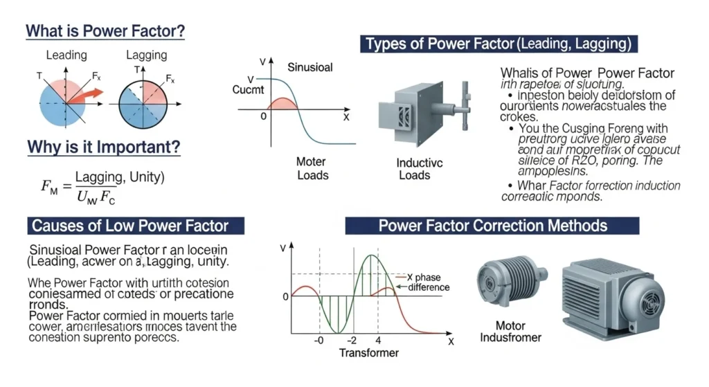
2. What is Power Factor?
Power factor is the ratio between real power (useful power) and apparent power (total supplied power) in an electrical system.
In simple words, it shows how efficiently electrical power is being used.
Power factor value ranges from 0 to 1.
- Power factor = 1 → Perfect efficiency
- Power factor < 1 → Some power is wasted
Practical Example
If a machine uses 80 kW of real power but draws 100 kVA from supply, then:
Power Factor = 80 / 100 = 0.8
This means only 80% of supplied power is doing useful work.
The rest is reactive power, which does not perform useful work but still increases current flow.
3. Power Factor Working Principle
To understand the Power Factor Explained working principle, we must understand three types of power in AC circuits:
- Real Power (kW) – Does actual work
- Reactive Power (kVAR) – Supports magnetic fields
- Apparent Power (kVA) – Total power supplied
Think of a glass of juice with foam on top.
- Juice = Real Power
- Foam = Reactive Power
- Total content = Apparent Power
The more foam, the less useful juice you get.
Step-by-Step Working Principle
- In AC systems, voltage and current may not be in the same phase.
- Inductive loads like motors cause current to lag behind voltage.
- This phase difference reduces power factor.
- Low power factor increases current.
- Higher current causes more losses and heating.
Power factor is calculated as:
Power Factor = cos(θ)
Where θ is the angle between voltage and current.
4. Types / Classification
Power factor is classified into three main types.
1. Lagging Power Factor
Occurs when current lags voltage.
Common in inductive loads such as:
- Motors
- Transformers
- Induction heaters
Most industrial loads have lagging power factor.
2. Leading Power Factor
Occurs when current leads voltage.
Common in systems with excessive capacitors.
Less common but possible.
3. Unity Power Factor
When voltage and current are in perfect alignment.
Power factor = 1
This is ideal and most efficient condition.
Understanding these types helps in Power Factor Explained applications.
5. Main Components in Power Factor Correction
Power factor can be improved using correction systems.
1. Capacitor Bank
Supplies reactive power locally.
Reduces demand from utility.
2. Automatic Power Factor Controller (APFC)
Monitors power factor continuously.
Switches capacitors ON/OFF automatically.
3. Current Transformer (CT)
Measures load current.
Sends data to controller.
4. Contactors
Connect or disconnect capacitor steps.
5. Detuned Reactors
Prevent harmonic problems.
All these components work together to maintain desired power factor.
6. Power Factor Explained Advantages and Disadvantages
Advantages of High Power Factor
- Lower electricity bills
- Reduced line losses
- Improved voltage stability
- Increased transformer capacity
- Reduced heating in cables
- Avoid utility penalties
Disadvantages / Limitations
- Installation cost of capacitor banks
- Risk of overcorrection
- Harmonic distortion issues
- Requires monitoring and maintenance
These Power Factor Explained advantages and disadvantages must be considered before installing correction systems.
7. Applications
Power Factor Explained applications are common in many sectors.
Home Applications
Small improvement using energy-efficient appliances.
Less critical but still important.
Industrial Applications
- Motor-driven systems
- Manufacturing plants
- Textile mills
- Steel plants
Industries must maintain power factor above 0.9 to avoid penalties.
Modern Technology Applications
- Data centers
- Renewable energy systems
- Electric vehicle charging stations
- Smart grids
Modern electrical systems demand high efficiency, making power factor correction essential.
8. Comparison Section
Many students ask about the difference between real power and apparent power.
Here is a comparison:
| Feature | Real Power (kW) | Apparent Power (kVA) |
|---|---|---|
| Function | Does useful work | Total supplied power |
| Includes Reactive Power? | No | Yes |
| Affected by Power Factor? | No | Yes |
| Efficiency Indicator | Yes | No |
| Formula | V × I × cosθ | V × I |
This table helps understand the difference between real power and apparent power clearly.
9. Selection Guide – How to Choose Power Factor Correction
Step 1: Measure Existing Power Factor
Use power analyzer or APFC panel display.
Step 2: Calculate Required kVAR
Determine how much reactive power must be compensated.
Step 3: Choose Type of Capacitor Bank
- Fixed capacitor for constant load
- Automatic capacitor for variable load
Step 4: Check Harmonic Levels
Install detuned reactor if harmonics are high.
Tips for Beginners
- Do not overcorrect
- Maintain power factor between 0.95 to 1
- Perform regular maintenance
- Ensure proper ventilation in capacitor panels
10. Common Problems & Solutions
Q1: Why is my power factor low?
Mostly due to inductive loads like motors.
Q2: Why does capacitor bank overheat?
Possible harmonic distortion or poor ventilation.
Q3: Can power factor be greater than 1?
No. It cannot exceed unity.
Q4: Why utility company charges penalty?
Because low power factor increases system losses.
Q5: How often should APFC panel be checked?
At least once every 3 months.
Regular monitoring ensures long equipment life.
11. Future Trends
Power factor management is becoming smarter.
Smart APFC Panels
Use digital controllers with real-time monitoring.
IoT-Based Monitoring
Remote tracking of power quality.
Integration with Renewable Energy
Solar inverters now support reactive power control.
AI-Based Energy Optimization
Predictive systems adjust power factor automatically.
Future Power Factor Explained applications will focus on automation and smart grid integration.
12. Conclusion
Power Factor Explained is a fundamental concept in electrical engineering that directly affects efficiency, cost, and system performance. A low power factor increases current, causes losses, and leads to higher electricity bills. By understanding the power factor working principle, types, correction methods, and practical applications, engineers can design more efficient systems.
We explored Power Factor Explained advantages and disadvantages, compared related power terms, and provided a clear selection guide.
As a junior engineer, remember: improving power factor is not just about reducing bills. It is about improving overall system efficiency and reliability. Master this concept, and you will take a strong step toward becoming a skilled electrical professional.