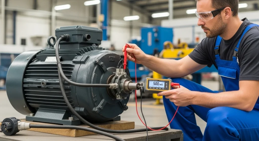
Imagine a technician inspecting an industrial motor before starting a large production machine. Everything appears normal from the outside—the cables are connected, the motor looks clean, and the power supply is stable. However, if the insulation inside the motor windings has weakened due to moisture, heat, or aging, turning on the system could lead to short circuits, equipment failure, or even electrical hazards. This is why engineers perform an Insulation Resistance Test before operating electrical equipment.
The insulation resistance test is one of the most important electrical maintenance tests used to check the health of insulation in cables, motors, transformers, and other electrical devices. Insulation acts as a protective barrier that prevents current from flowing where it should not. If this insulation becomes weak or damaged, leakage currents can occur, leading to serious problems.
For electrical engineers, technicians, and students, understanding insulation resistance testing is essential for maintaining safe and reliable electrical systems. This test helps detect insulation deterioration before it causes costly failures.
In this article, you will learn the Insulation Resistance Test working principle, types, components, Insulation Resistance Test applications, and the Insulation Resistance Test advantages and disadvantages. The explanation is written in simple language to help beginners clearly understand how this important electrical test works.
2. What is an Insulation Resistance Test?
The Insulation Resistance Test is a diagnostic electrical test used to measure the resistance of insulation materials that separate electrical conductors from each other or from ground.
The purpose of this test is to ensure that insulation is strong enough to prevent leakage current.
Simple Explanation
Electrical insulation is designed to block current flow between conductors and ground. However, insulation can degrade over time due to moisture, heat, dust, or mechanical damage.
The insulation resistance test measures how well the insulation prevents unwanted current flow.
High resistance indicates good insulation, while low resistance indicates insulation problems.
Practical Example
Consider an electric motor in a factory. Over time, the motor windings may absorb moisture from the environment. This moisture weakens insulation between the windings and the motor frame.
By performing an insulation resistance test, a technician can detect this problem before the motor fails.
This preventive maintenance helps avoid equipment damage and costly downtime.
3. Insulation Resistance Test Working Principle
The Insulation Resistance Test working principle is based on applying a high DC voltage to insulation and measuring the resulting leakage current.
If the insulation is healthy, very little current will flow, resulting in high resistance.
If insulation is weak or damaged, more current will leak through, indicating lower resistance.
Step-by-Step Operation
- The test instrument applies a DC voltage to the insulation.
- The voltage is applied between conductor and ground or between conductors.
- Insulation opposes current flow.
- The instrument measures leakage current through insulation.
- Resistance is calculated using Ohm’s law.
Simple Analogy
Think of insulation as a wall preventing water from leaking. If the wall is strong, almost no water passes through. If cracks develop, water starts leaking.
Similarly, weak insulation allows electrical leakage.
Typical Test Voltages
Different equipment requires different test voltages.
Common test voltages include:
- 250 V
- 500 V
- 1000 V
- 2500 V
- 5000 V
Higher voltage tests are used for large industrial equipment.
4. Types / Classification of Insulation Resistance Tests
Several types of insulation tests are used depending on the purpose of testing.
Spot Reading Test
This is the simplest insulation resistance test.
Features
- Measurement taken after one minute of voltage application
- Provides quick insulation condition check
Applications
- Routine maintenance testing
- Small electrical equipment
Time Resistance Test
This test observes insulation resistance over a longer time.
Features
- Resistance readings taken at multiple time intervals
- Helps detect insulation contamination
Polarization Index (PI) Test
This test compares insulation resistance readings at two time points.
Common formula:
PI = Resistance at 10 minutes / Resistance at 1 minute
Features
- Indicates insulation quality
- Used for motors and generators
Dielectric Absorption Ratio (DAR) Test
This test measures insulation resistance at different time intervals.
Features
- Detects insulation moisture and contamination
These tests provide deeper insights into insulation condition.
5. Main Components of Insulation Resistance Test Equipment
The equipment used for insulation resistance testing contains several important components.
Megohmmeter (Megger)
The megohmmeter is the primary testing instrument.
Function:
- Generates high DC voltage
- Measures insulation resistance in megaohms
Test Leads
Test leads connect the instrument to the equipment being tested.
Function:
- Conduct test voltage
- Ensure accurate measurements
DC Voltage Generator
This internal circuit produces the test voltage required for insulation testing.
Function:
- Apply stable test voltage
Measurement Circuit
This circuit measures the leakage current.
Function:
- Calculate insulation resistance value
Display Unit
Modern testers include digital displays.
Function:
- Show resistance values
- Provide diagnostic information
6. Advantages of Insulation Resistance Test
Understanding the Insulation Resistance Test advantages and disadvantages helps engineers maintain electrical systems effectively.
Advantages
- Detects insulation deterioration early
- Prevents electrical failures
- Improves equipment reliability
- Enhances electrical safety
- Helps schedule preventive maintenance
- Reduces repair costs
Because of these benefits, insulation resistance testing is widely used in electrical maintenance.
7. Disadvantages / Limitations
Despite its usefulness, insulation resistance testing also has limitations.
- Cannot detect all types of insulation faults
- Moisture and temperature affect test results
- Requires proper safety precautions
- Incorrect testing procedures may damage equipment
Therefore, trained technicians must perform the test carefully.
8. Insulation Resistance Test Applications
There are many Insulation Resistance Test applications in electrical engineering.
Electric Motors
Used to check insulation between motor windings and frame.
Power Cables
Ensures cable insulation is intact before installation.
Transformers
Detects insulation degradation in transformer windings.
Generators
Helps monitor insulation condition of generator stator windings.
Electrical Panels
Used to verify insulation integrity of wiring and circuits.
These applications make insulation resistance testing essential for safe electrical operation.
9. Comparison: Insulation Resistance Test vs Continuity Test
Understanding the difference between insulation resistance test and continuity test is important.
| Feature | Insulation Resistance Test | Continuity Test |
|---|---|---|
| Purpose | Check insulation quality | Check circuit connection |
| Voltage Used | High DC voltage | Low voltage |
| Measurement | Resistance in megaohms | Low resistance |
| Application | Insulation systems | Wiring and circuits |
Both tests are important but serve different purposes.
10. Selection Guide
Choosing the correct insulation resistance test equipment depends on several factors.
Test Voltage Range
Select instruments with voltage suitable for the equipment.
Measurement Range
Ensure the tester can measure high resistance values.
Safety Features
Modern testers include protection against overload and incorrect connections.
Portability
Field technicians often prefer lightweight portable testers.
Digital Features
Advanced instruments offer data logging and automatic calculations.
Selecting the right instrument improves testing accuracy.
11. Common Problems & Solutions
Why is insulation resistance low?
Possible causes:
- Moisture in insulation
- Dirt or contamination
- Insulation aging
Solution:
Dry equipment and clean insulation surfaces.
Why do readings change during testing?
Resistance may increase over time as insulation absorbs charge.
This behavior is normal for many insulation materials.
Why are results inconsistent?
Possible reasons include:
- Temperature changes
- Poor test connections
Always perform tests under stable conditions.
12. Future Trends
Electrical testing technology is evolving rapidly.
Smart Insulation Testers
Modern testers include digital storage and automatic analysis.
Remote Monitoring Systems
Industrial plants increasingly monitor insulation health remotely.
Predictive Maintenance
Advanced software predicts insulation failure before it occurs.
Integration with Smart Grids
Future electrical systems will include automated insulation monitoring.
These technologies will improve electrical reliability and safety.
13. Conclusion
The Insulation Resistance Test is a critical maintenance procedure used to evaluate the condition of electrical insulation in cables, motors, transformers, and other equipment. By measuring insulation resistance, engineers can detect insulation deterioration before it leads to dangerous failures.
Understanding the Insulation Resistance Test working principle, types, and Insulation Resistance Test applications allows technicians to maintain electrical systems safely and efficiently. This test plays a vital role in preventive maintenance programs across industries.
Although insulation resistance testing has some limitations, its ability to identify insulation problems early makes it one of the most valuable diagnostic tools in electrical engineering. As testing technologies continue to advance, insulation monitoring will become even more accurate and automated.
For students, technicians, and engineers, mastering insulation resistance testing is essential for ensuring safe and reliable electrical installations.